Uploads by Amallen
Jump to navigation
Jump to search
This special page shows all uploaded files.
| Date | Name | Thumbnail | Size | Description | Versions |
|---|---|---|---|---|---|
| 00:01, 20 June 2008 | Transceiver2-jpg.JPG (file) | 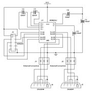 |
36 KB | Schematic for the ADM202 Tranceiver Circuit Board. Also displayed is the manner in which the DB9 serial ports should be connected to the board. | 1 |
| 00:59, 20 June 2008 | Transceiver diagram.jpg (file) | 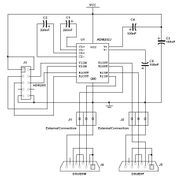 |
36 KB | Schematic for the ADM202 Tranceiver Circuit Board. Also displayed is the manner in which the DB9 serial ports should be connected to the board. | 1 |
| 01:25, 20 June 2008 | Finished transceiver.jpg (file) | 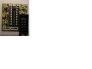 |
149 KB | Transceiver board with all components soldered into place. | 1 |
| 01:28, 20 June 2008 | Transceiver with wires.jpg (file) | 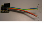 |
148 KB | Transceiver board complete with ADM202 chip connected and ribbon cables soldered into place to be connected to DB9 serial ports. | 1 |
| 01:57, 20 June 2008 | Transceiver board.jpg (file) | 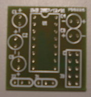 |
145 KB | Transceiver board without any components in place. | 2 |
| 01:59, 20 June 2008 | Soldered transceiver.jpg (file) | 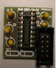 |
147 KB | Transceiver board with soldered components in place. | 1 |
| 02:02, 20 June 2008 | Completed transceiver.jpg (file) |  |
144 KB | Completed transceiver board with all components including the ADM202 chip and ribbon cables soldered into place to eventually be used to connect to the DB9 serial ports. | 1 |
| 02:31, 20 June 2008 | Tranceiver attached.jpg (file) | 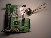 |
144 KB | Transceiver board attached via ribbon cable to the serial header soldered into the router's board. | 1 |
| 02:57, 20 June 2008 | Front sticker.jpg (file) | 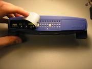 |
655 KB | Front of the router with the sticker peeled back. | 1 |
| 02:58, 20 June 2008 | Front.jpg (file) | 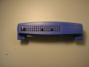 |
702 KB | Front of the router with the sticker removed. | 1 |
| 21:58, 20 June 2008 | Serial ports.JPG (file) | 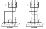 |
19 KB | Diagram of wiring to connect the two DB9 serial ports to the transceiver board. | 1 |
| 22:11, 20 June 2008 | Transceiver diagram.JPG (file) | 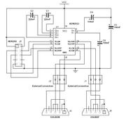 |
39 KB | Schematic for the ADM202 Tranceiver Circuit Board. Also displayed is the manner in which the DB9 serial ports should be connected to the board. | 4 |
| 22:12, 20 June 2008 | Transceiver schematic.JPG (file) | 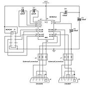 |
39 KB | Schematic for the ADM202 Tranceiver Circuit Board. Also displayed is the manner in which the DB9 serial ports should be connected to the board. | 1 |
| 22:14, 20 June 2008 | Serial ports diagram.JPG (file) | 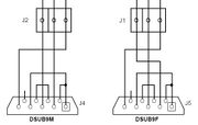 |
20 KB | Diagram of wiring to connect the two DB9 serial ports to the transceiver board. | 1 |
| 22:51, 20 June 2008 | Serial ports done1.jpg (file) | 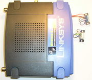 |
147 KB | Overhead picture of what the router will look like after the DB9 serial ports are correctly soldered into place, but before they have been screwed and secured into the router's case. | 1 |
| 22:53, 20 June 2008 | Serial ports done2.jpg (file) |  |
144 KB | Front view of what the router will look like after the DB9 serial ports are correctly soldered into place, but before they have been screwed and secured into the router's case. | 1 |
| 22:58, 25 June 2008 | Complete transceiver board.jpg (file) | 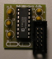 |
144 KB | Transceiver board with components in place. | 1 |
| 23:07, 2 July 2008 | Serial ports done.jpg (file) |  |
146 KB | Front view of what the router will look like after the DB9 serial ports are correctly soldered into place, but before they have been screwed and secured into the router's case. | 1 |
| 23:12, 2 July 2008 | Modified front.jpg (file) |  |
146 KB | Front of the router with two holes drilled in to fit the serial ports and side holes drilled for bolts to secure each serial port. | 3 |
| 23:12, 2 July 2008 | Drilled front.jpg (file) |  |
146 KB | Front of the router with two holes drilled in to fit the serial ports and side holes drilled for bolts to secure each serial port. | 1 |
| 23:20, 2 July 2008 | Attach Back.jpg (file) | 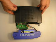 |
149 KB | 1 | |
| 23:20, 2 July 2008 | Attach Front.jpg (file) | 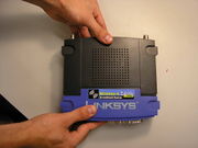 |
145 KB | 1 | |
| 23:22, 2 July 2008 | Complete.jpg (file) | 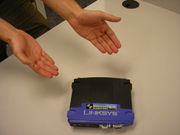 |
147 KB | 1 |