Difference between revisions of "Serial adapter diagrams"
Jump to navigation
Jump to search
| Line 1: | Line 1: | ||
== RJ45/DB9 adapters == | == RJ45/DB9 adapters == | ||
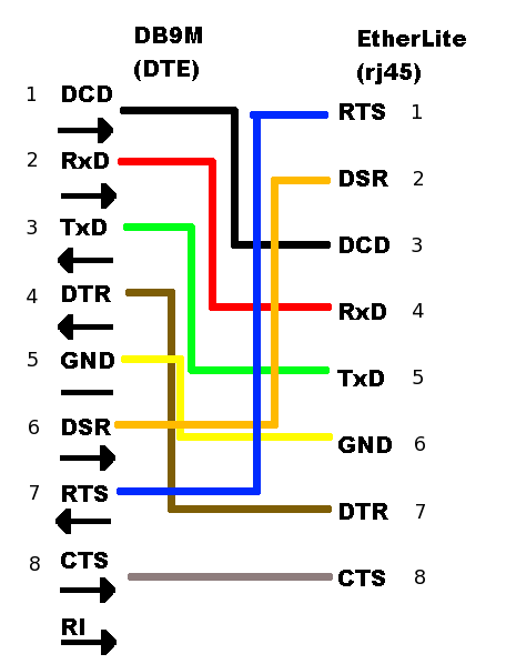
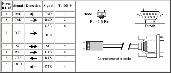
Below are diagrams for RJ45 to DB9 adapters allowing connection between an Etherlite serial bay and XINU backends in a pool. The first diagram is for UART 0 (DTE). The second diagram is for the platform-dependent UART 1 (DCE). | Below are diagrams for RJ45 to DB9 adapters allowing connection between an Etherlite serial bay and XINU backends in a pool. The first diagram is for UART 0 (DTE). The second diagram is for the platform-dependent UART 1 (DCE). | ||
| − | [[Image:DTE.png|thumb|900px|left|UART 0, DTE]] | + | [[Image:DTE.png|thumb|900px|left|UART 0, DTE]]{{clr}} |
| − | [[Image:DCE.png|thumb|900px|left|UART 1, DCE]] | + | [[Image:DCE.png|thumb|900px|left|UART 1, DCE]]{{clr}} |
== EtherLite to Baytech == | == EtherLite to Baytech == | ||
Revision as of 20:18, 12 July 2007
RJ45/DB9 adapters
Below are diagrams for RJ45 to DB9 adapters allowing connection between an Etherlite serial bay and XINU backends in a pool. The first diagram is for UART 0 (DTE). The second diagram is for the platform-dependent UART 1 (DCE).
EtherLite to Baytech
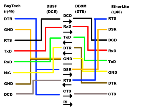
The third diagram represents the connection between the between the Baytech serial-controlled power strip and the EtherLite terminal annex. Note that for the particular RJ45/DB9 connectors used in this research, the colors of diagram three can be mated with the Signal labels from the first two diagrams (i.e. RTS = DB9 pin 7 = Blue).
Null Modem
The null modem adapter is required to make connections between available UART 1 ports on two machines (UART 0 being in use for communicating results through xinu-console).


