Difference between revisions of "Modify the Linksys hardware"
(→Task Three: Install MAX233A Transceiver: Drafted this section) |
(→Steps: Added Task Zero recommendation of installing openWRT) |
||
| Line 52: | Line 52: | ||
==Steps== | ==Steps== | ||
| + | |||
| + | === Task Zero: Install OpenWRT [Recommended] === | ||
| + | |||
| + | While the purpose of this HOWTO is a hardware modification, the fruits of our labor will be in software functionality. In order to place a light at the end of this tunnel, it would be a good idea to [[install OpenWRT|HOWTO:Install_OpenWRT]] using the instructions provided on this wiki. OpenWRT by default runs a console on UART0, and so once the connection is made properly you need only to send an <enter> into the input and you will be provided with a root console on the router. It's a very satisfying way of confirming that you've done everything correctly. | ||
=== Task One: Opening the Router === | === Task One: Opening the Router === | ||
Revision as of 13:38, 5 March 2007
Work in progress...
Contents
Parts List
| Quantity | Part Name | Details | Part / Model Number | Price |
|---|---|---|---|---|
| 1 | LinkSys WRT54GL Router | 802.11b/g wireless broadband router | LinkSys WRT54GL | ~$65.00 |
| 1 | Ribbon cable | 28 AWG, 10 conductor, 25' | Jameco 643508CM | $4.99 |
| 1 | IDC socket connector | 0.1”, 10 conductor | Jameco 32491CM | $0.25 |
| 1 | IDC shrouded header | 0.1”, 10 conductor | Jameco 67811CM | $0.33 |
| 1 | RS232 Transmitter/Receiver | IC 2DVR/2RCVR RS232 5V 20-DIP | DigiKey MAX233CPP-ND | $7.45 |
| 2 | Two (2) DB9 Female | 22AWG,SOLDER CUP | Jameco 15771CM | $0.59 |
Tools List
- Soldering Iron
- Dremel tool (for cutting holes in plastic case)
Steps
Task Zero: Install OpenWRT [Recommended]
While the purpose of this HOWTO is a hardware modification, the fruits of our labor will be in software functionality. In order to place a light at the end of this tunnel, it would be a good idea to HOWTO:Install_OpenWRT using the instructions provided on this wiki. OpenWRT by default runs a console on UART0, and so once the connection is made properly you need only to send an <enter> into the input and you will be provided with a root console on the router. It's a very satisfying way of confirming that you've done everything correctly.
Task One: Opening the Router
As others have done, I will defer to Void Main, who provides nice illustrated opening instructions.
DO NOTE: This is where the warranty on the router is voided! (But really, you know there's no real fun to be had unless a warranty gets voided somewhere.)
Task Two: Attaching the Serial Header
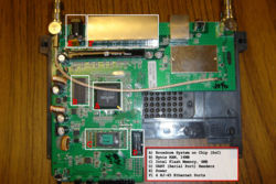
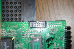
Now that your PCB is naked, locate the serial header holes provided by LinkSys. This would be a grid of 10 holes (5x2) located on the bottom-right corner of the board when the antennae stubs are on top (see the top-down photo for clarification). These ten holes hold all of the input and output for the two serial interfaces--UART0, and UART1--on the device. (OpenWRT by default runs a console on UART0, so we have something to look forward to here!)
Now, we could just solder wires right onto these holes, but a by placing a nice 10-pin header on the board we can easily attach and detach a 10 connection cable. This is where you will use your soldering iron solder the IDC shrouded header onto the board.
This will be the only soldering that you have to do on the LinkSys PCB. The rest of the work will be done wiring the MAX233A transceiver correctly and it just has to be plugged it into this header.
Task Three: Install wiring for MAX233A RS232 Transmitter/Receiver
Using information on the Wiring page, make the connections from the IDC shrouded header to the MAX233A RS232 Transmitter/Receiver chip. As you can see from the Build Pictures page, we did this with the ribbon cable from our parts list. The IDC socket connector goes on one end of the cable, and the correct connections are made to the RS232 Transmitter/Receiver on the other. Because we will be mounting our DB9 connectors to the front of the case, this will allow for easy disconnection and opening of the case. In terms of cable length, try and decide where you are going to mount the MAX233A on the outer case so you can estimate correctly. Do not wire up the Two (2) DB9 Female Connectors just yet, as it would be a better idea to mount them first.


