Wiring
Jump to navigation
Jump to search
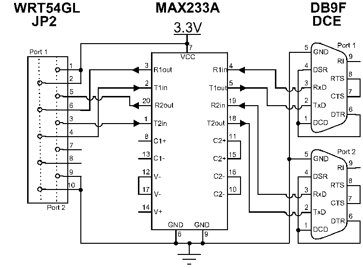
The diagram on the left represents the UART head on the main board of the router. The left pins (2,6,4,8,10) represent the data that is sent and received from the first serial port, the right pins (1,5,3,7,9) the second serial port.
The diagram in the middle represents the MAX233A transceiver needed to convert the voltage used to transmit signals in the router (3.3V) to the RS-232 standard signals to send over the serial port.
The diagrams on the rights represent two standard DB9F serial ports wired to be DCEs.
Please note that the diagrams do NOT represent actual placement of the pins on the hardware, which may have been moved to simplify the diagram.
