Pictures
Jump to navigation
Jump to search
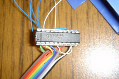


This is a picture of the MAX233A transceiver chip we used to convert the digital serial signal to proper RS232 voltages. Our picture shows a wire-wrap socket to hold the transceiver chip, but this was our prototype. In practice, now that the correct connections have been confirmed experimentally, we will solder leads directly to a 20-pin standard DIP socket, which can be glued on its side to the inside of the front case piece. This allows access to the receiver chip (in case an electrical mishap damages it,) while still allowing easy opening and closing of the case.

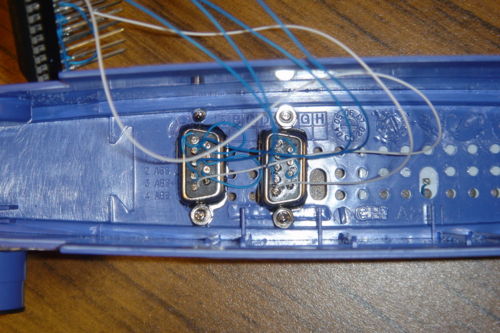
This is the final version of the faceplate of our router, with the two external serial ports attached and ready to go. The fit is quite tight; you may wish to consider only installing one jack (you only need port 0 to communicate with the router,) or installing them horizontally instead of vertically.


