File:Transceiver diagram.JPG
Jump to navigation
Jump to search
Transceiver_diagram.JPG (584 × 569 pixels, file size: 39 KB, MIME type: image/jpeg)
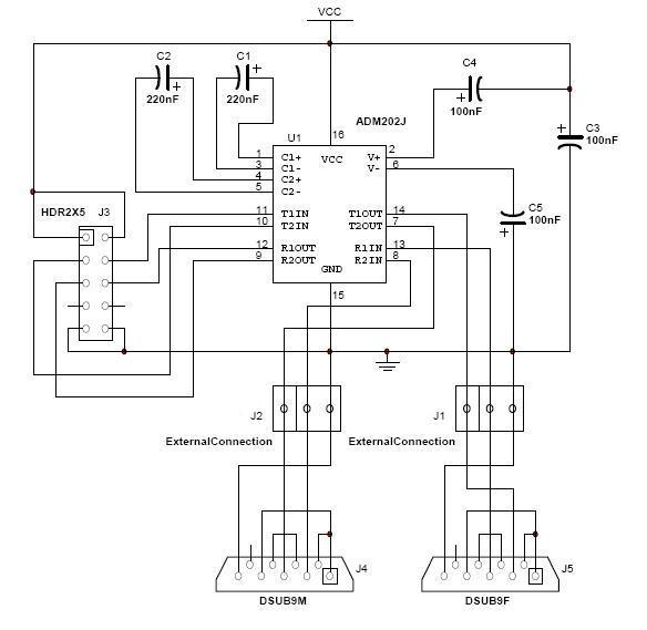
Schematic for the ADM202 Tranceiver Circuit Board. Also displayed is the manner in which the DB9 serial ports should be connected to the board.
File history
Click on a date/time to view the file as it appeared at that time.
| Date/Time | Thumbnail | Dimensions | User | Comment | |
|---|---|---|---|---|---|
| current | 22:11, 20 June 2008 |  | 584 × 569 (39 KB) | Amallen (talk | contribs) | Schematic for the ADM202 Tranceiver Circuit Board. Also displayed is the manner in which the DB9 serial ports should be connected to the board. |
| 22:09, 20 June 2008 |  | 584 × 569 (39 KB) | Amallen (talk | contribs) | Schematic for the ADM202 Tranceiver Circuit Board. Also displayed is the manner in which the DB9 serial ports should be connected to the board. | |
| 01:52, 20 June 2008 |  | 584 × 569 (39 KB) | Amallen (talk | contribs) | Schematic for the ADM202 Tranceiver Circuit Board. Also displayed is the manner in which the DB9 serial ports should be connected to the board. | |
| 00:04, 20 June 2008 |  | 567 × 569 (36 KB) | Amallen (talk | contribs) | Schematic for the ADM202 Tranceiver Circuit Board. Also displayed is the manner in which the DB9 serial ports should be connected to the board. |
You cannot overwrite this file.
File usage
The following file is a duplicate of this file (more details):
There are no pages that use this file.
