HOWTO:Modify the ASUS hardware
Contents
- 1 Summary
- 2 Before Starting
- 3 Steps to Modify the Hardware
- 3.1 Task One: Open the Router
- 3.2 Task Two: Attach the Serial Header
- 3.3 Task Three: Create space for access to serial port on the router
- 3.4 Task Four: Creating the ADM202 Transceiver Circuit Board
- 3.5 Task Five: Attach Transceiver Board to the Router
- 3.6 Task Six: Attach Transceiver Board to DB9 Serial Ports
- 3.7 Task Seven: Creating a box case for the component
- 4 What to do next?
Summary
The purpose of this walk through is to explain how to add hardware to the ASUS wl-330gE router to take advantage of the serial port on the router and use it to communicate with the serial console for Xinu. This communication is important for interacting with the Common Firmware Environment's, or CFE, command line interface which is necessary to run Xinu on the router.
Before Starting
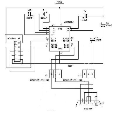
NOTE: The following lists all the necessary parts. However, the following tutorial describes assembling the transceiver on one of our custom transceiver boards. One could assemble the parts of the entire transceiver properly without the board, but with more difficulty. Our transceiver board design is freely available for public use. Transceiver schematic is in postscript format, suitable for XCircuit. Transceiver PCB layout is in PCB format. Transceiver fabrication tarball contains Gerber photoplotter and CNC drill files suitable for professional fabrication. (No warranty express or implied, obviously.)
Parts List
| Quantity | Part Name | Details | Part / Model Number | Price |
|---|---|---|---|---|
| 1 | ASUS wl-330gE Router | 802.11b/g wireless access point | ASUS wl-330gE | ~$40.00 |
| 1 | IDC socket connector | 4 pin header | Jameco | |
| 1 | IDC socket connector | 5 pin header | Jameco | |
| 1 | IDC shrouded double header | 0.1”, 10 conductor | Jameco 67811CM | $0.33 |
| 1 | ADM202 Transceiver Chip | Serial Transceiver ADM202EAN | Jameco 1800464 | $1.60 |
| 2 | Capacitor 220 nF | Tantalum,.22uF,35V,10% | Jameco 33507 | $0.18 |
| 3 | Capacitor 100 nF | Tantalum,.1uF,35V,10% | Jameco 33488 | $0.22 |
| 1 | DB9 Female | 22AWG,SOLDER CUP | Jameco 15771CM | $0.59 |
(We provide this parts list as a data point; we offer no guarantees about current prices, and it is not our intent to endorse any particular vendor.)
Tools List
- Soldering Iron
- Dremel tool (for cutting holes in plastic case)
- Continuity Tester (Multimeter, or some other way of checking for proper connections)
- Voltmeter (Multimeter will work for this, too)
Steps to Modify the Hardware
Task One: Open the Router
Using a screwdriver, remove the two nails located underneath the router and gently remove the top of the router from the bottom, revealing the PCB.
DO NOTE: This is where the warranty on the router is voided!
Task Two: Attach the Serial Header
The PCB is easily removable at this state from the router. Located in the center of the PCB is the Broadcom BCM5354 chip. Above the chip are four holes that are aligned vertically. The four holes represent the input and output for the serial interface, along with the 3.3 volt power and ground sources for the serial port.
For easier connectivity, we can use a 4-pin header on the board to easily attach and detach a 4 connection cable. Use a soldering iron to solder the 4-pin header onto the board.
Task Three: Create space for access to serial port on the router
Using a dremel or other power tool, carefully cut out a rectangular shaped hole on the faceplate of the router. The hole should be cut above the words “Portable” and it should be 3 mm wide and 1 cm in height, or enough to see the serial port through the hole. This will be used for a 4-wired cable to attach the router to the transceiver board, detailed in step seven.
Task Four: Creating the ADM202 Transceiver Circuit Board
A transceiver circuit is needed to convert the 3.3 volt serial signals from the router to conventional RS-232 serial voltages. To do this, we need a small square of “perf board”, or other circuit prototyping techniques. A soldering iron needs to be used to solder the components onto the board.
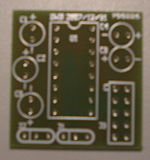
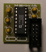
Solder the shrouded double header, the socket, and the capacitors onto the board. The direction of the pins matter due to their polarity.
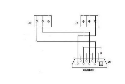
Once the components have been placed on the board, use a continuity tester to check the connection between the header soldered into the router's board and the socket on the transceiver board. Now the ADM202 chip can be inserted onto the board. Next, wires need to be soldered onto the bottom of the transceiver board. Since this router only has one transceiver board, only three of the holes need wires. Under the J2 label, solder wires into the two left most holes. Under the J1 label, which is under the chip, solder a wire on the right most hole.
Task Five: Attach Transceiver Board to the Router
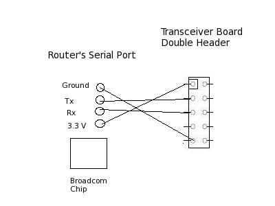
The easiest way to accomplish this is to use an 4-wire audio cable between the router's serial header and the shrouded double header on the transceiver board. Using the 4-pin header on the router, connect the four wires from the audio cable into the 4-pin header. On the transceiver board, follow the diagram to match the corresponding cables on the shrouded double header, but using a 5-pin serial header to easily attack to the shrouded double header.
Task Six: Attach Transceiver Board to DB9 Serial Ports
Since the router is very small, it will not have space to place the DB9 Serial Port. Therefore, a small container needs to be created to encase all of the components. This will be discussed in step seven. Take the three wires from the transceiver board and attach them to the DB9 female according to the diagram. Make sure that the solder cups 1, 4, and 6 are connected to each other and solder cups 7 and 8 are connected to each other in the DB9 Female serial port. Notice that in the case of the DB9 Female the T1OUT pin of the ADM202 transceiver chip needs to be connected to solder cup 2, the R1IN pin of the ADM202 transceiver chip needs to be connected to solder cup 3, and the ground needs to be connected to solder cup 5.
Now you can use a continuity tester to make sure that all the connections are good and that no wires or solder cups are touching. The router should be placed back it its case, and the box keeping all the components together should separate the router from the transceiver board. It will be very bad if the circuit board and the transceiver board were to touch.
Task Seven: Creating a box case for the component
The ASUS router is small, but because of this, there is no space for the DB9 female serial port, the adaptor, the relay, and the transceiver board. Because of this, a box is needed to enclose all of these components together. The box should have holes cut out for the DB9 female serial port, the power adapter and the Ethernet port. Also, a small barrier needs to be placed between the transceiver board and the relay so they do not meet. The PCB can be safely placed inside the ASUS router case.
What to do next?
Connect UART0 (the DB9 Female serial port) to a computer and follow the next HOWTO on using a PC to connect to a modified router.
This work is supported in part by NSF grant DUE-CCLI-0737476.
