File list
Jump to navigation
Jump to search
This special page shows all uploaded files.
| Date | Name | Thumbnail | Size | User | Description | Versions |
|---|---|---|---|---|---|---|
| 05:53, 28 August 2006 | Embedsysdiag.png (file) | 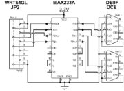 |
6 KB | Justin | The wiring diagram of the serial ports we added. | 1 |
| 18:15, 1 September 2006 | Mainboard.jpg (file) | 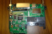 |
440 KB | Michael | Picture of the main board on the WRT54GL | 1 |
| 18:22, 1 September 2006 | Serial.jpg (file) | 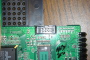 |
274 KB | Michael | 1 | |
| 18:25, 1 September 2006 | Attach-back.jpg (file) | 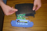 |
553 KB | Michael | 1 | |
| 18:25, 1 September 2006 | Attach-front.jpg (file) |  |
404 KB | Michael | 1 | |
| 18:26, 1 September 2006 | Faceplate.jpg (file) |  |
288 KB | Michael | 1 | |
| 18:26, 1 September 2006 | Final.jpg (file) |  |
457 KB | Michael | 1 | |
| 18:27, 1 September 2006 | Maxim.jpg (file) |  |
339 KB | Michael | 1 | |
| 19:37, 8 September 2006 | Cfe-broadcom.pdf (file) | 362 KB | Michael | The 145 page document from broadcom explaining what CFE is (and is not). | 1 | |
| 20:08, 8 September 2006 | Wrt54gl-layout.jpg (file) | 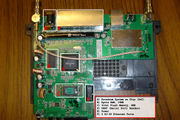 |
215 KB | Phinze | Top down photo of the WRT54GL with the basic board features marked. | 1 |
| 20:28, 8 September 2006 | Embedsys2.ps (file) | 18 KB | Justin | The .ps version of the wiring diagram. | 1 | |
| 21:09, 15 September 2006 | Opening-linksys.jpg (file) |  |
20 KB | Phinze | Opening the linksys router. Cropped from a picture on Void Main's site [http://voidmain.is-a-geek.net/redhat/wrt54g_revival.html]. | 1 |
| 04:34, 5 March 2007 | MAX233A.png (file) | 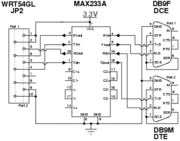 |
8 KB | Michael | 1 | |
| 03:33, 22 March 2007 | XINU-Lab-schematic.gif (file) |  |
56 KB | Brylow | 3 | |
| 19:24, 1 June 2007 | Te jtag cable.png (file) | 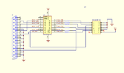 |
18 KB | Jpicotte | Total Embedded buffered jtag cable | 1 |
| 19:34, 1 June 2007 | Wiggler.png (file) | 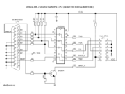 |
27 KB | Jpicotte | OpenWRT buffered jtag cable | 1 |
| 17:00, 20 June 2007 | TtyUartInteraction.png (file) | 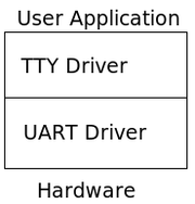 |
6 KB | Agember | Diagram of the interaction between hardware, UART driver, TTY driver, and user application. | 2 |
| 17:44, 20 June 2007 | Red x.png (file) |  |
1 KB | Phinze | Red X stolen from Wikipedia. http://en.wikipedia.org/wiki/Image:Red_x.png | 1 |
| 18:17, 22 June 2007 | Broom.png (file) |  |
74 KB | Michael | From [http://en.wikipedia.org/wiki/Image:Broom_icon.svg|wikipedia] | 1 |
| 19:09, 6 July 2007 | WRT350N.png (file) | 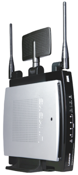 |
81 KB | Jpicotte | 1 | |
| 16:43, 11 July 2007 | Clockimportant.gif (file) |  |
7 KB | Agember | 1 | |
| 16:47, 11 July 2007 | Clockimportant.png (file) |  |
4 KB | Agember | 1 | |
| 19:51, 11 July 2007 | TtyDriver.png (file) |  |
9 KB | Agember | 2 | |
| 19:52, 11 July 2007 | UartAsyncDriver.png (file) | 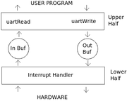 |
14 KB | Agember | 2 | |
| 21:00, 11 July 2007 | Broom icon.png (file) | 3 KB | Agember | 1 | ||
| 19:04, 12 July 2007 | DCE.png (file) |  |
20 KB | Jpicotte | RJ45/DB9 serial adapter | 1 |
| 19:43, 12 July 2007 | BaytechWiring.png (file) | 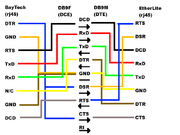 |
8 KB | Jpicotte | Wiring diagram for Baytech to EtherLite connection | 1 |
| 23:51, 18 July 2007 | Disambig.png (file) |  |
5 KB | Michael | 1 | |
| 21:30, 23 July 2007 | JTAGunbuffered.png (file) | 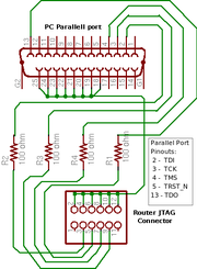 |
11 KB | Jpicotte | updated jtag cable with parallel port pinouts | 2 |
| 16:15, 4 October 2007 | Impcode.png (file) | 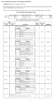 |
149 KB | Jpicotte | MIPS EJTAG Specification description of implementation code register contents | 1 |
| 21:39, 13 February 2008 | XMMS-02-13-2008a.jpg (file) |  |
92 KB | Phinze | rotated | 2 |
| 21:39, 13 February 2008 | XMMS-02-13-2008b.jpg (file) |  |
148 KB | Phinze | XINU M&M's close up. | 1 |
| 03:50, 21 February 2008 | Netaa network daemons plan.pdf (file) | 169 KB | Agember | Diagram of the network daemons plan for the Embedded Systems netaa team. | 1 | |
| 03:12, 26 February 2008 | Netaa network send plan.pdf (file) | 99 KB | Agember | 1 | ||
| 17:56, 29 February 2008 | 145ozmm.jpg (file) |  |
42 KB | Michael | For reference, this is 3-45oz (145oz) bags of M&Ms. | 1 |
| 19:40, 11 April 2008 | TCPIP State Transition Diagram.pdf (file) | 26 KB | CVuong | 1 | ||
| 00:12, 2 May 2008 | Mms full 01.jpg (file) |  |
56 KB | Agember | Full M&M jar - jar contains 4.5 56oz bags of M&Ms | 1 |
| 00:12, 2 May 2008 | Mms full 02.jpg (file) |  |
73 KB | Agember | Full M&M jar - jar contains 4.5 56oz bags of M&Ms | 1 |
| 00:01, 20 June 2008 | Transceiver2-jpg.JPG (file) | 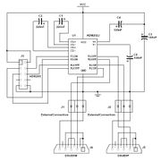 |
36 KB | Amallen | Schematic for the ADM202 Tranceiver Circuit Board. Also displayed is the manner in which the DB9 serial ports should be connected to the board. | 1 |
| 00:59, 20 June 2008 | Transceiver diagram.jpg (file) | 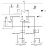 |
36 KB | Amallen | Schematic for the ADM202 Tranceiver Circuit Board. Also displayed is the manner in which the DB9 serial ports should be connected to the board. | 1 |
| 01:25, 20 June 2008 | Finished transceiver.jpg (file) | 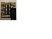 |
149 KB | Amallen | Transceiver board with all components soldered into place. | 1 |
| 01:28, 20 June 2008 | Transceiver with wires.jpg (file) | 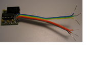 |
148 KB | Amallen | Transceiver board complete with ADM202 chip connected and ribbon cables soldered into place to be connected to DB9 serial ports. | 1 |
| 01:57, 20 June 2008 | Transceiver board.jpg (file) | 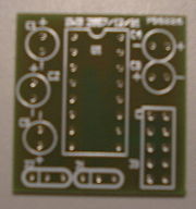 |
145 KB | Amallen | Transceiver board without any components in place. | 2 |
| 01:59, 20 June 2008 | Soldered transceiver.jpg (file) | 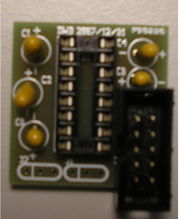 |
147 KB | Amallen | Transceiver board with soldered components in place. | 1 |
| 02:02, 20 June 2008 | Completed transceiver.jpg (file) |  |
144 KB | Amallen | Completed transceiver board with all components including the ADM202 chip and ribbon cables soldered into place to eventually be used to connect to the DB9 serial ports. | 1 |
| 02:31, 20 June 2008 | Tranceiver attached.jpg (file) | 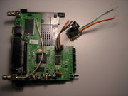 |
144 KB | Amallen | Transceiver board attached via ribbon cable to the serial header soldered into the router's board. | 1 |
| 02:57, 20 June 2008 | Front sticker.jpg (file) | 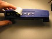 |
655 KB | Amallen | Front of the router with the sticker peeled back. | 1 |
| 02:58, 20 June 2008 | Front.jpg (file) | 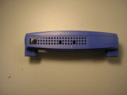 |
702 KB | Amallen | Front of the router with the sticker removed. | 1 |
| 21:58, 20 June 2008 | Serial ports.JPG (file) | 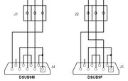 |
19 KB | Amallen | Diagram of wiring to connect the two DB9 serial ports to the transceiver board. | 1 |
| 22:11, 20 June 2008 | Transceiver diagram.JPG (file) | 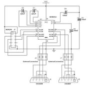 |
39 KB | Amallen | Schematic for the ADM202 Tranceiver Circuit Board. Also displayed is the manner in which the DB9 serial ports should be connected to the board. | 4 |