Difference between revisions of "Serial adapter diagrams"
| (10 intermediate revisions by 2 users not shown) | |||
| Line 1: | Line 1: | ||
| − | == | + | == RJ45/DB9 adapters == |
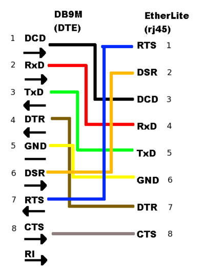
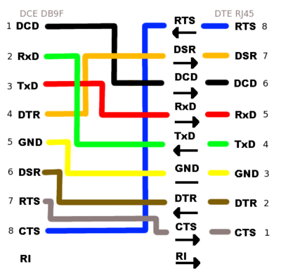
| − | Below are diagrams for RJ45 to DB9 adapters allowing connection between an Etherlite serial bay and XINU backends in a pool. The first diagram is for | + | Below are diagrams for RJ45 to DB9 adapters allowing connection between an [[HOWTO:Build Backend Pool|Etherlite serial bay and XINU backends]] in a pool. The first diagram is for UART 0 (DTE). The second diagram is for the platform-dependent UART 1 (DCE). |
| − | [[Image: | + | [[Image:DB9M.png|thumb|400px|left|UART 0, DTE]]<br clear="all" /> |
| − | [[Image: | + | [[Image:NullModem.png|thumb|400px|left|UART 1, DCE]]<br clear="all" /> |
| − | [[Image: | + | == Null Modem == |
| + | The null modem adapter is required to make connections between available UART 1 ports on two machines. The above UART 1 diagram functions as a null modem when connecting directly to other backends, as well as to the EtherLite serial bay. | ||
| + | |||
| + | == EtherLite to Baytech == | ||
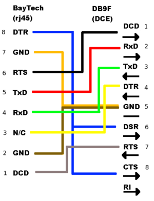
| + | The third diagram represents a connection between the between a Baytech serial-controlled power strip and the EtherLite terminal annex. The final two diagrams are the Baytech/Etherlite diagram broken into two parts, representing the mating of two individual RJ45/DB9 adapters. | ||
| + | [[Image:BaytechWiring.png|thumb|500px|left|Wiring diagram for Baytech to Etherlite connection]] | ||
| + | <br clear="all" /> | ||
| + | [[Image:DB9M.png|thumb|300px|left|same as UART 0 diagram above]]<br clear="all" /> | ||
| + | [[Image:baytech.png|thumb|300px|left|Baytech RJ45 to DB9F]] | ||
| + | <br clear="all" /> | ||
Latest revision as of 23:58, 30 September 2008
RJ45/DB9 adapters
Below are diagrams for RJ45 to DB9 adapters allowing connection between an Etherlite serial bay and XINU backends in a pool. The first diagram is for UART 0 (DTE). The second diagram is for the platform-dependent UART 1 (DCE).
Null Modem
The null modem adapter is required to make connections between available UART 1 ports on two machines. The above UART 1 diagram functions as a null modem when connecting directly to other backends, as well as to the EtherLite serial bay.
EtherLite to Baytech
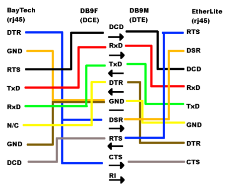
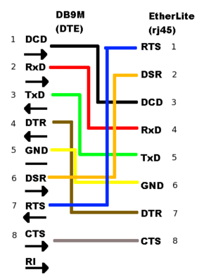
The third diagram represents a connection between the between a Baytech serial-controlled power strip and the EtherLite terminal annex. The final two diagrams are the Baytech/Etherlite diagram broken into two parts, representing the mating of two individual RJ45/DB9 adapters.
